
What “CNC” Actually Means (And Why It Matters for Manufacturers)
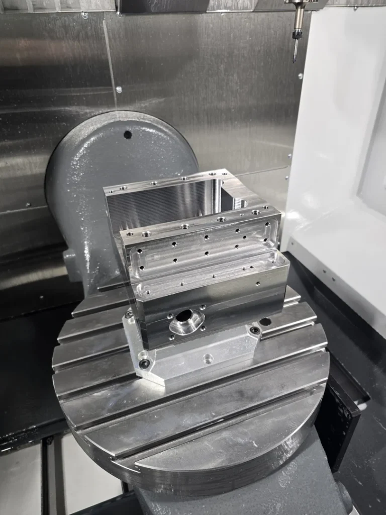
CNC — short for Computer Numerical Control — is the automated control of machine tools using a computer. Instead of an operator manually guiding a cutting tool, a CNC system reads a set of programmed instructions and moves the machine with precise, repeatable accuracy.
Here’s the short version:
| Question | Quick Answer |
|---|---|
| What does CNC stand for? | Computer Numerical Control |
| What does it do? | Automates machine tool movement using programmed instructions |
| How accurate is it? | Within +/- 0.002 inches per foot using ballscrew technology |
| What does it replace? | Manual machining guided by a human operator |
| Who uses it? | Aerospace, automotive, tube/pipe manufacturing, medical, and more |
If you work in tube and pipe manufacturing, you’ve likely seen the impact firsthand. Inconsistent cuts, poor weld bead removal, and variable part quality are often symptoms of processes that haven’t yet taken full advantage of what modern automated machining can deliver. CNC technology exists precisely to solve those problems — removing human variability from repetitive, precision-critical tasks.
The numbers back this up. Modern CNC systems can increase productivity by up to 70% compared to manual machining for repetitive production runs, and can cut production time for complex parts by 50–80%.
I’m Jarek Szpakowski, and at ITSE Inc. in Lake Zurich, IL, I’ve spent years applying CNC precision to heavy-duty tube mill equipment, ID/OD scarfing systems, and custom bead chopping solutions for manufacturers across the US. In this guide, I’ll break down everything you need to know about CNC machining — no jargon, no fluff.
What is CNC and How Does It Work?
To understand how a CNC system operates, it helps to contrast it with manual machining. In a traditional machine shop, a machinist manually turns handwheels to move a cutting tool along a metal workpiece. The accuracy of the cut depends entirely on the operator’s physical coordination, visual judgment, and experience.
With Computer numerical control, we replace those manual handwheels with high-precision electric motors. These motors are directed by a computerized controller that reads digitized instructions.
This movement relies on a standard Cartesian coordinate system. In a basic 3-axis machine:
- The X-axis represents horizontal movement (left to right).
- The Y-axis represents lateral movement (front to back).
- The Z-axis represents vertical movement (up and down).
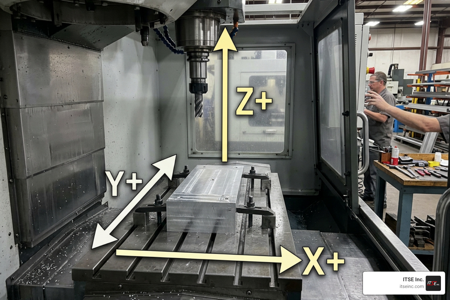
By coordinating these three axes simultaneously, a machine can carve out complex three-dimensional shapes with incredible speed. Advanced systems add rotational axes (commonly referred to as the A, B, and C axes) to tilt and rotate the workpiece or the cutting tool, enabling complex geometries without manual repositioning.
The brain of the machine is the positioning control system. It translates digital code into physical movement. This digital code is divided into two primary programming languages:
- G-code: Commands that control the physical motion of the machine, telling it where to move, how fast to get there, and what path to follow.
- M-code: Miscellaneous commands that manage auxiliary functions, such as turning the coolant on or off, starting or stopping the spindle, and executing automatic tool changes.
Together, these codes form a complete manufacturing recipe that the machine executes flawlessly, piece after piece.
The Evolution from Numerical Control to Modern CNC
The journey to modern automation started in the late 1940s and early 1950s. The earliest systems, known simply as Numerical Control (NC), did not use computers. Instead, they relied on punched paper tape or cards to feed physical instructions to pneumatic and mechanical relays. While for their time, these early NC machines were massive, expensive, and incredibly tedious to program. If you made a single mistake in your code, you had to physically punch a brand-new roll of tape.
As microprocessors emerged and computing costs declined rapidly in the 1970s and 1980s, NC evolved into CNC. Computers were integrated directly into the machine frames, allowing operators to store multiple programs, edit code on the fly, and simulate toolpaths before making a single cut.
As of June 2026, the technology has reached extraordinary heights. Today’s trends focus on deep artificial intelligence (AI) integration, real-time sensor feedback, cloud-based programming, and hybrid manufacturing (which combines additive 3D printing and subtractive milling in a single machine envelope). This relentless innovation is driving massive commercial expansion; the global CNC machine market is projected to reach $117.5 billion by 2027, growing at a steady compound annual growth rate (CAGR) of 7.3%.
Key Components of a Modern CNC System
Every modern industrial system relies on a network of mechanical and electrical components working in perfect harmony:
- The Controller (CPU): The computer that interprets the program and sends electrical signals to the drive motors.
- Drive Motors (Servos and Steppers): Stepper motors move in fixed, incremental steps and are common in lighter-duty equipment. Servo motors, on the other hand, are used in heavy industrial settings. They work with rotary encoders to provide continuous feedback on speed and position.
- Closed-Loop Feedback: Over 90% of modern industrial systems utilize closed-loop feedback controls. Unlike open-loop systems that simply send a command and “hope” the motor moved to the right spot, closed-loop systems constantly monitor the tool’s actual position using encoders, correcting minor errors in real-time.
- Ballscrews: To convert the rotational force of the motors into linear movement along the axes, industrial machines use precision ballscrews. By utilizing recirculating ball bearings inside a threaded nut, ballscrew technology minimizes friction and eliminates mechanical play. This allows modern machines to achieve positioning accuracy within +/- 0.002 inches per foot.
- The Spindle: The rotating shaft that holds and spins the cutting tool at speeds ranging from a few thousand to over 24,000 RPM.
- The Bed and Frame: The rigid foundation of the machine, typically made of cast iron or heavy welded steel to absorb vibrations and maintain alignment under heavy cutting forces.
For control software, industrial shops use proprietary systems, but the open-source community has also developed incredibly robust alternatives like LinuxCNC open-source control, which is widely used to run everything from custom retrofitted mills to complex robotic arms.
Main Types of Machining Equipment and Their Applications
Because different manufacturing tasks require different cutting actions, the industry has developed several specialized types of machinery.
Milling Machines and Lathes
Milling and turning are the two pillars of subtractive manufacturing.
CNC Mills: In a milling machine, the raw material remains stationary (clamped to the machine bed), while a multi-point cutting tool rotates at high speeds to carve away material. These machines excel at creating flat surfaces, slots, pockets, and complex 3D contours. While basic mills operate on three axes, advanced facilities utilize multi-axis milling (such as 4-axis and 5-axis setups) to rotate the part dynamically. This capability is crucial for high-precision components, which is why local shops rely on specialized Precision 5-Axis CNC Machining Services in Lake Zurich to handle complex aerospace, medical, and industrial parts.
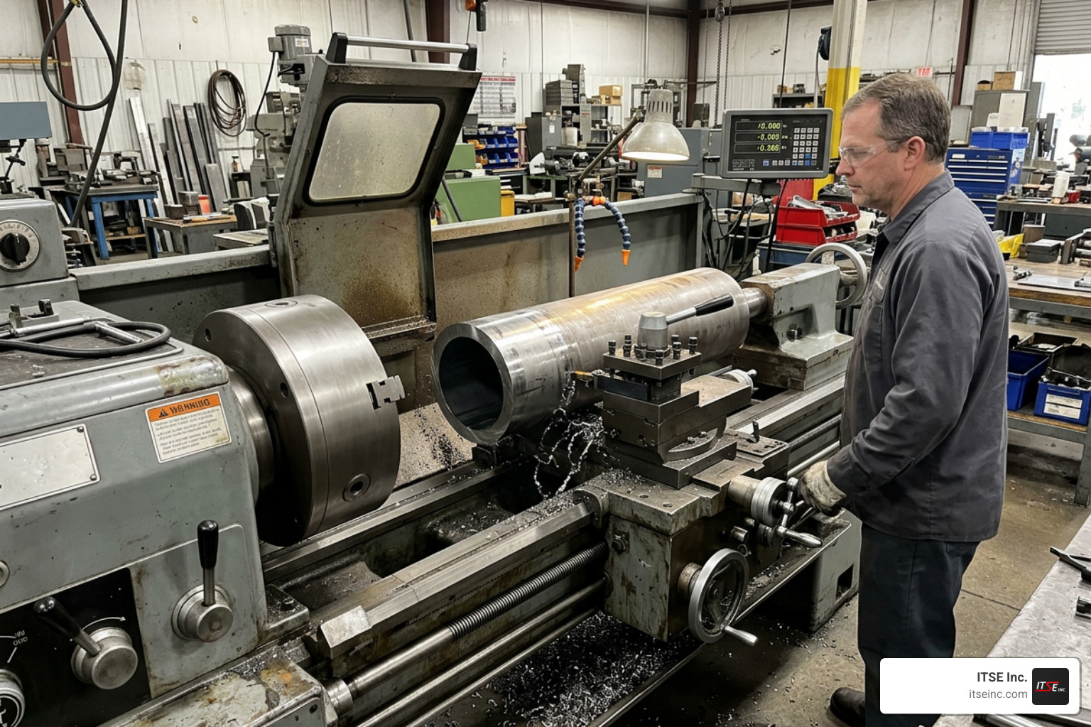
CNC Lathes (Turning Centers): In a lathe, the process is reversed: the raw material is clamped in a chuck and spun rapidly, while a stationary single-point cutting tool is pressed against it to peel away material. This is the ideal process for producing cylindrical parts like shafts, bushings, and custom rollers. Modern turning centers often feature “live tooling,” which allows small milling cutters to operate on the part while it is held in the lathe, combining turning and milling into a single operation.
For businesses looking for reliable partners to handle these operations, utilizing advanced CNC machining services ensures highly accurate subtractive manufacturing tailored to demanding industrial standards.
Advanced Cutting Technologies
Beyond physical spinning cutters, we use thermal, chemical, and electrical forces to process materials:
- Laser Cutting: Uses a highly focused, high-power laser beam to melt or vaporize material along a programmed path. It is incredibly fast and clean, making it a staple of precision metal fabrication.
- Water Jet Cutters: These systems blast a mixture of water and abrasive garnet through a tiny nozzle at pressures up to 60,000 PSI. Because it uses no heat, waterjet cutting is perfect for materials that are sensitive to thermal distortion, such as thick steel, stone, and composites.
- Electrical Discharge Machining (EDM): Often called spark machining, EDM uses rapid electrical sparks discharged between an electrode tool and a conductive workpiece submerged in a dielectric fluid. Wire EDM uses a continuously moving thin wire to slice through hardened steels and exotic alloys with extreme precision, easily creating sharp 90-degree internal corners that are impossible to make with circular milling cutters.
The differences in material removal rates between these technologies are staggering. While conventional milling machines can process materials at rates up to 8 million cubic millimeters per minute (mm³/min), high-precision sinker EDM averages a much slower 100 mm³/min. However, EDM makes up for its speed with unmatched accuracy on hardened metals.
In the Chicagoland manufacturing corridor, these advanced capabilities are highly sought after. Companies seeking high-precision components rely on advanced machining setups to maintain strict quality and production standards across demanding industrial applications.
Software, Programming, and Operational Best Practices
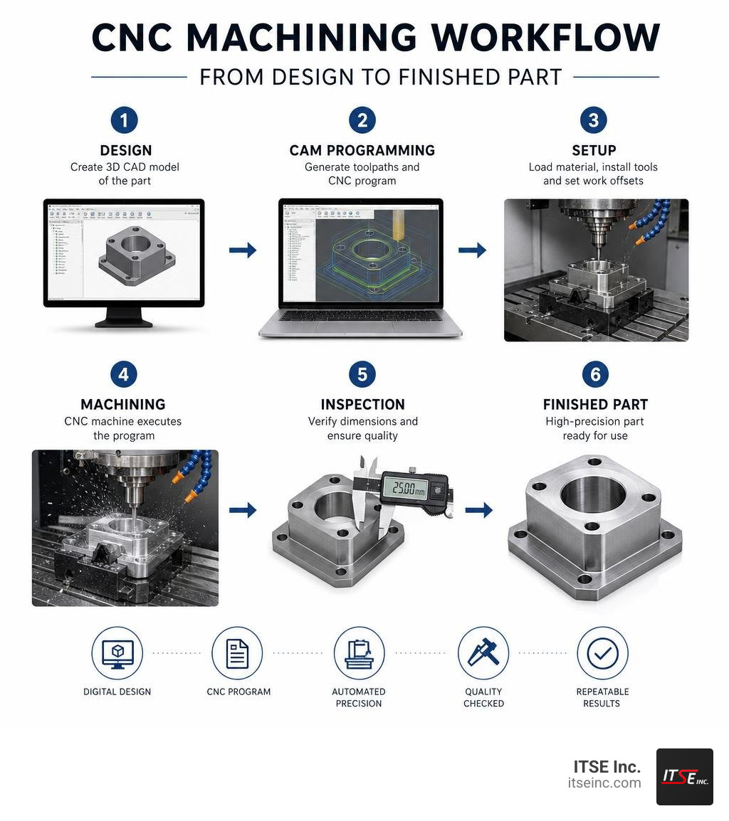
The process of taking a part from a concept to a finished physical product follows a structured digital workflow:
- CAD (Computer-Aided Design): The engineer designs a 3D solid model of the part using CAD software.
- CAM (Computer-Aided Manufacturing): The CAM programmer imports the CAD model and defines how the machine will actually cut the part. This includes choosing the cutting tools, setting the toolpath strategies, and calculating the optimal speeds (RPM) and feeds (travel speed).
- Post-Processor: Because every machine controller reads code slightly differently, a post-processor translator convert the CAM toolpaths into the specific G-code and M-code language required by the target machine.
For smaller shops or hobbyists, desktop systems like the Nomad 4 Desktop CNC – Carbide 3D come bundled with user-friendly CAD/CAM software to make this workflow seamless. On the other end of the spectrum, heavy-duty industrial systems, such as a CNC Mill T-Rex with steel frame for milling with excellent precision, require professional-grade CAM software to optimize toolpaths for high-speed machining in tough materials.
G-Code and M-Code Programming
While CAM software automates code generation, a skilled operator must understand how to read and modify the raw program. Let’s look at how G-codes and M-codes function in a simple program:
- G00 (Rapid Positioning): Moves the machine axes to a specific coordinate at maximum speed. This is used to position the tool close to the part before cutting begins.
- G01 (Linear Interpolation): Moves the tool in a straight line at a controlled feed rate to cut material.
- G02 / G03 (Circular Interpolation): Moves the tool in a clockwise (G02) or counter-clockwise (G03) arc.
- M03 (Spindle On, Clockwise): Starts the rotation of the cutting tool.
- M05 (Spindle Stop): Stops the spindle from spinning.
- M06 (Tool Change): Commands the automatic tool changer to swap out the current tool for a different one.
A typical snippet of a program might look like this:
- N10 G90 G00 X0 Y0 Z1.0 (Sets absolute coordinates, rapidly moves to the starting point, and holds the tool 1 inch above the part)
- N20 M03 S3000 (Starts the spindle spinning clockwise at 3,000 RPM)
- N30 G01 Z-0.1 F10.0 (Feeds the cutter straight down 0.1 inches into the material at a speed of 10 inches per minute)
- N40 G01 X5.0 Y0 F20.0 (Cuts a straight line along the X-axis to the 5-inch mark)
- N50 M05 (Stops the spindle)
- N60 G00 Z1.0 (Rapidly retracts the tool safely away from the material)
Safety Protocols and Preventing Machine Crashes
A “crash” occurs when a machine tool collides with a fixture, a clamp, or the machine frame itself. Because industrial spindles rotate with immense torque and axes move with thousands of pounds of force, a crash can cause tens of thousands of dollars in damage, destroy tooling, and pose a severe safety hazard to operators.
To prevent crashes and maintain a safe working environment, we implement several layers of protection:
- Homing and Zeroing: Many machines do not know where they are in physical space when first powered on. Operators must perform a manual “homing” sequence to drive the axes to physical limit switches, establishing a reliable “machine zero” reference point.
- Simulation Software: Before running a program on physical metal, we load the code into simulation software. This models the entire machine envelope—including clamps, vises, and raw stock—to detect potential collisions digitally.
- Physical Limit Switches: Electronic sensors placed at the extreme ends of each axis to automatically cut power to the drive motors if the machine attempts to travel past its safe physical limits.
- Enclosures and Interlocks: Modern industrial machines are fully enclosed in steel housings with safety glass windows. Electronic interlocks prevent the machine from running if the doors are open, protecting operators from flying chips and pressurized coolant.
Comparing Automated Machining to Other Manufacturing Technologies
To understand where CNC fits in modern production, it helps to compare it directly with other common manufacturing methods:
| Feature | CNC Machining | 3D Printing (Additive) | Manual Machining |
|---|---|---|---|
| Process Type | Subtractive (removes material) | Additive (builds layer-by-layer) | Subtractive (removes material) |
| Setup Time | Moderate to High (programming & fixtures) | Low (direct from digital model) | Very Low (no programming needed) |
| Production Speed | Fast (for medium to high volumes) | Slow (hours per single part) | Slow (highly dependent on operator) |
| Material Range | Metals, plastics, woods, composites | Limited plastics, select metals | Metals, plastics, woods |
| Surface Finish | Excellent (smooth, highly precise) | Rough (visible layer lines) | Variable (depends on operator skill) |
| Repeatability | Exceptional (perfectly identical parts) | High (but minor layer variations) | Low (prone to human fatigue/error) |
For manufacturers looking to integrate high-efficiency automated subtractive processes into their production lines, investing in professional CNC Machining services is the fastest way to scale up part quality and consistency.
Machining vs. 3D Printing
The primary difference lies in subtractive versus additive methodologies. 3D printing builds parts layer-by-layer from the ground up, allowing for highly complex internal geometries (like hollow lattices) that are physically impossible to cut with a milling tool.
However, 3D printing faces significant material constraints, slower build times, and weaker structural integrity due to the laminated nature of the layers. CNC machining carves parts out of solid, homogenous blocks of extruded metal or molded plastic, ensuring maximum strength, superior surface finishes, and tighter dimensional tolerances.
Machining vs. Manual Methods
While manual machining is still incredibly useful for quick, simple repairs or making a single basic bracket, it cannot compete with automation in production environments.
Manual machining relies on human hands and eyes, making it slow and prone to errors. By automating the process, we eliminate human fatigue, dramatically reduce scrap rates, and achieve a level of consistency where the 1,000th part is identical to the very first. It is this transition from manual to automated methods that regularly yields up to a 70% increase in shop floor productivity.
Frequently Asked Questions about Automated Machining
What is the difference between open-loop and closed-loop systems?
An open-loop system sends movement commands to stepper motors but has no way of verifying if the motor actually executed the movement. If the tool hits a hard spot in the metal and stalls, the controller keeps running the program, ruining the part.
A closed-loop system uses rotary encoders or linear scales to continuously track the actual position of the axes. If a servo motor falls behind its programmed position by even a fraction of a millimeter, the controller instantly adjusts the current to correct the position, ensuring near-perfect accuracy.
What materials can be processed using automated machinery?
Modern systems can process almost any solid material, provided you select the correct cutting tools, spindle speeds, and feed rates:
- Metals: Aluminum, alloy steels, stainless steel, brass, copper, and titanium.
- Plastics: Delrin (Acetal), ABS, polycarbonate, acrylic, Nylon, and high-performance PEEK.
- Woods: Hardwoods, softwoods, MDF, and plywoods.
- Composites: Carbon fiber and fiberglass (though these require specialized dust collection to protect guide rails and operators).
How does mechanical backlash affect precision?
Backlash is the tiny amount of “play” or clearance in a mechanical drive system when an axis reverses direction. If a gear or lead screw has play, the motor will turn slightly before the axis actually starts moving.
Over time, this play degrades precision, especially when cutting circles or complex curves where axes must constantly reverse direction. To combat this, high-end machines use precision preloaded ballscrews and advanced control software that automatically adds “backlash compensation” to the motor commands.
Conclusion
At ITSE Inc., we believe that understanding the fundamentals of automation is the first step toward building a more efficient, profitable production line. Whether you are optimizing a high-speed tube mill or looking to improve the quality of your finished products, integrating precision control is the key to unlocking consistent success.
From our headquarters in Lake Zurich, IL, and our service locations across the Chicagoland area, we design and manufacture custom tube mill equipment, OD bead choppers, and ID scarfing systems built to withstand the rigors of heavy industrial production. We combine rugged, US-made construction with the precision engineering necessary to keep your operations running smoothly.
Ready to take your manufacturing precision to the next level? Explore our range of high-performance Products, learn more about our specialized CNC Machining capabilities, or contact our engineering team in Lake Zurich today to discuss a custom solution tailored to your exact production needs.