
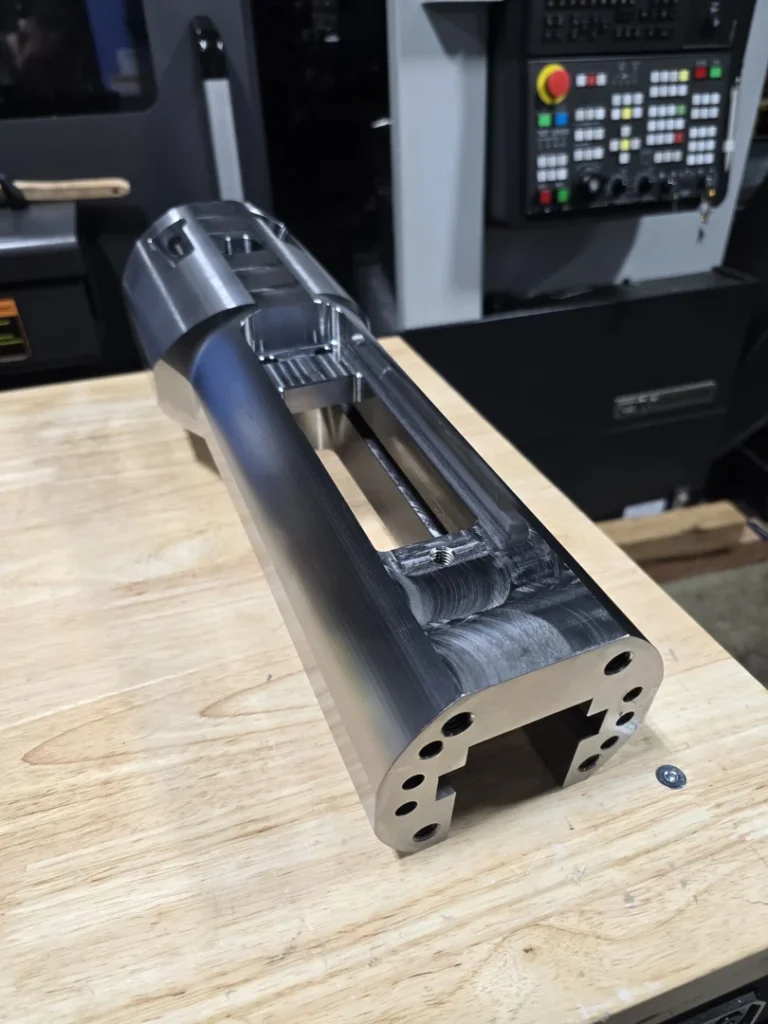
When You Need a Metal Prototype Fast, Here’s What to Know
Prototype CNC machining is the fastest way to turn a CAD file into a functional metal or plastic part — without building a mold or waiting weeks.
Here’s a quick answer to what most people want to know:
| Question | Quick Answer |
|---|---|
| What is it? | Subtractive manufacturing that cuts parts from solid material blocks using computer-controlled tools |
| How fast? | Most prototypes ship in 1–3 working days |
| How accurate? | Tolerances as tight as ±0.0001 in. (0.0025 mm) |
| Common materials | Aluminum, stainless steel, titanium, brass, PEEK, ABS |
| Best for | Functional testing, design validation, low-volume custom parts |
| vs. 3D printing | More precise, stronger parts, wider material options — but typically higher cost per part |
Getting a prototype wrong is expensive. A part that looks right in CAD but fails on the shop floor costs you time, money, and momentum. That’s especially true in heavy manufacturing, where components like scarfing tools, bead choppers, and tube mill parts need to perform under real load — not just look the part.
The good news: modern CNC prototyping has compressed what used to take weeks into days, with the same material properties as your final production run.
I’m Jarek Szpakowski, and at ITSE Inc. in Lake Zurich, IL, we’ve built our reputation on prototype CNC machining for demanding industrial applications — from custom scarfing systems to precision tube mill components. If you’re a manufacturer who needs parts that work right the first time, this guide is written for you.
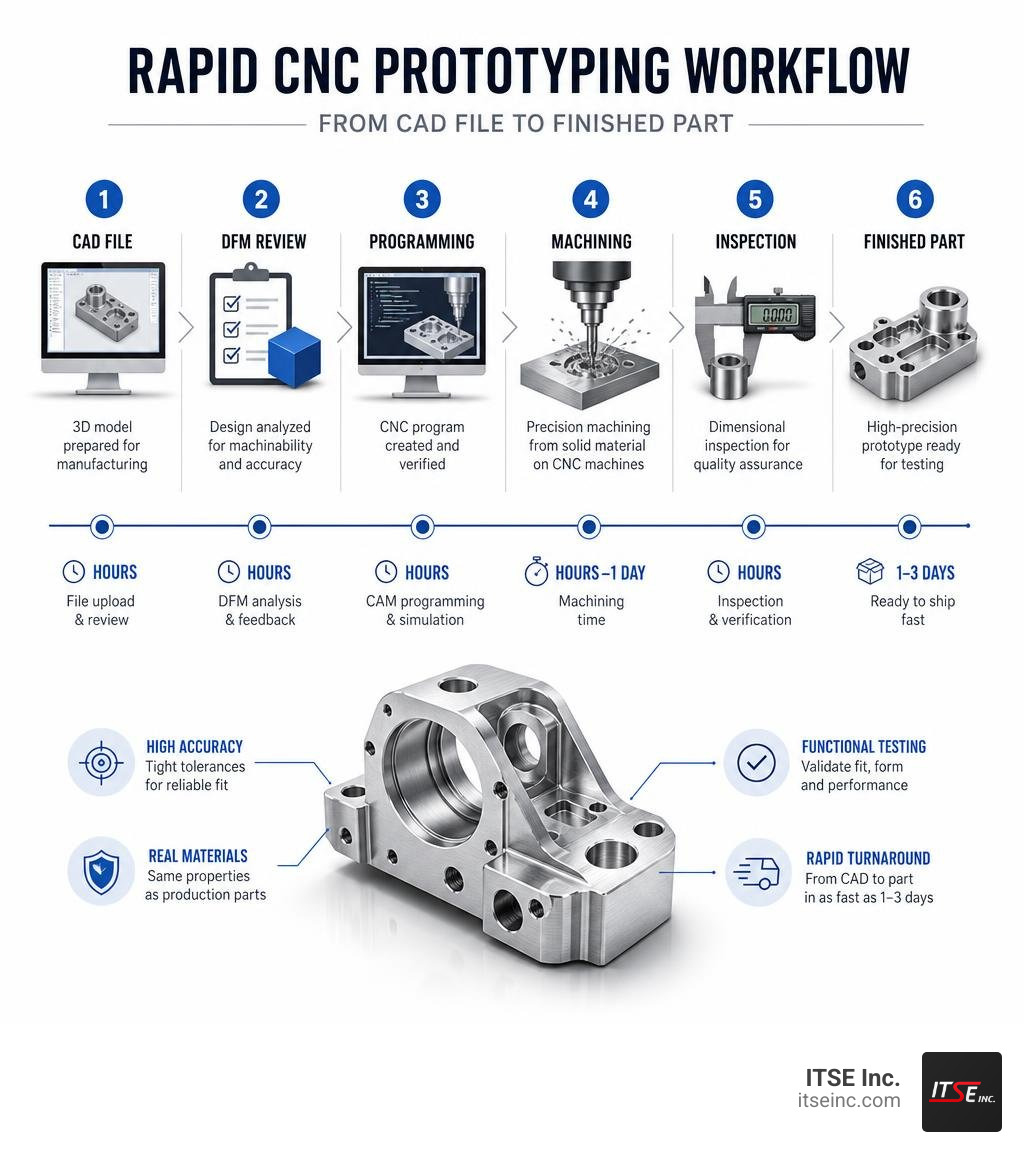
What is Prototype CNC Machining and How Does It Work?
At its core, prototype CNC machining is a subtractive manufacturing process. While additive manufacturing, like 3D printing, builds parts layer by layer, CNC machining starts with a solid block of raw material, often called a billet, and carves away material using high-speed rotating cutting tools. This process is guided by Computer Numerical Control (CNC) technology, which translates digital designs into physical reality with incredible speed and accuracy.
The journey from a digital concept to a physical prototype follows a highly structured, automated workflow:
- CAD Modeling: The designer creates a detailed 3D model of the prototype using Computer-Aided Design (CAD) software.
- CAM Programming: The CAD file is imported into Computer-Aided Manufacturing (CAM) software. Here, an engineer defines the toolpaths, spindle speeds, and cutting parameters.
- G-code Generation: The CAM software translates the visual toolpaths into G-code, the universal programming language of CNC machines. This code tells the machine exactly where to move, how fast to spin, and when to change cutting tools.
- Machine Setup: The raw material block is securely fixtured inside the machine, and the required cutting tools are loaded into the tool changer.
- Machining Execution: The CNC machine executes the G-code, rapidly milling, turning, or drilling the block into the finished part.
Depending on the geometry of your part, we utilize different machining configurations to get the job done efficiently.
3-Axis Milling
This is the most common and cost-effective form of CNC milling. The cutting tool moves along three linear axes: X (left to right), Y (front to back), and Z (up and down). While highly efficient for simpler geometries, parts with features on multiple sides require manual repositioning, which can add setup time. Standard 3-axis setups are highly effective for rapid turnaround times when geometry is kept straightforward.
5-Axis Milling
For highly complex, organic, or multi-faceted shapes, we turn to 5-axis machining. In addition to the three linear axes, the machine or the workpiece rotates along two additional rotational axes (A and B). This allows the cutting tool to approach the workpiece from virtually any angle in a single setup, eliminating manual re-handling, improving surface finish, and achieving incredibly tight geometric tolerances. For local projects requiring extreme geometric complexity, our precision CNC machining services utilize advanced multi-axis centers to deliver production-ready components.
CNC Turning
If your prototype is cylindrical, such as a shaft, roller, custom pin, or threaded fitting, CNC turning is the ideal process. The raw material block rotates at high speed while a stationary cutting tool removes material along its profile. Modern mill-turn centers combine turning and milling capabilities, allowing us to machine complex cylindrical parts with cross-holes, flats, and slots in a single operation.
Whether you need a single proof-of-concept piece or a small test batch, utilizing professional CNC machining services allows you to upload your CAD files, receive detailed manufacturability feedback, and kick off the machining process quickly.
The Core Benefits of Prototype CNC Machining
When developing custom industrial equipment, selecting the right prototyping method is a critical decision. While 3D printing is fantastic for early-stage form studies, prototype CNC machining remains the undisputed heavyweight champion for functional testing and engineering validation.
Here is why engineers rely on CNC machined prototypes:
Unmatched Structural Integrity
Unlike 3D printed parts, which are built layer by layer and often suffer from weakness along the Z-axis (delamination), CNC machined prototypes are carved from a single, solid block of homogeneous material. This means the prototype possesses the exact same isotropic mechanical properties—such as tensile strength, impact resistance, and fatigue life—as the final production part. This is absolutely critical for heavy industrial equipment, where parts must withstand extreme mechanical stresses, hydraulic pressures, and thermal cycles without failing.
Microscopic Accuracy and Tight Tolerances
When a prototype must interface with existing machinery, thousandths of an inch matter. CNC machining can easily maintain standard linear tolerances of ±0.005 in. (0.13 mm). For high-precision applications, such as medical instruments, aerospace components, or custom tube mill tooling, multi-axis machines can hold tolerances as tight as ±0.0001 in. (0.0025 mm). This level of precision is virtually impossible to achieve with standard additive manufacturing methods.
Production-Grade Surface Finishes
A prototype often needs to do more than just fit; it must perform under specific surface conditions. CNC prototype machining supports a vast array of surface finishes, including:
- As-Milled: The standard finish, showing subtle tool marks. Great for structural, internal parts.
- Bead Blasting: Propels abrasive media to create a uniform, matte, non-reflective surface that hides tool marks.
- Anodizing (Type II & III): An electrochemical process that increases corrosion resistance, improves surface hardness, and allows for color customization.
- Black Oxide & Plating: Adds chemical resistance and reduces friction.
Rapid Turnaround Lead Times
Time is money in product development. While traditional tooling-based prototyping (like injection molding or die casting) can take weeks or months to design and manufacture molds, CNC rapid prototyping bypasses the tooling phase entirely. Most prototype machining projects can be completed in just 1 to 3 working days. Even complex, multi-sided parts using advanced materials can be delivered in less than a week, allowing engineering teams to iterate rapidly.
For businesses looking to validate designs with speed and precision, partnering with an experienced shop for rapid prototype machining ensures that your physical samples are delivered with the exact mechanical characteristics required for real-world testing.
Why CNC Machining is the Gold Standard for Metal Prototyping
When it comes to metal prototyping, nothing matches the versatility and reliability of CNC machining. It bridges the gap between digital design and physical deployment by allowing engineers to test their designs using the exact metals specified for final production.
Infinite Material Versatility
Whether your design requires lightweight structural components or heavy-duty wear-resistant tooling, CNC machining supports virtually any solid metal alloy:
- Aluminum (6061-T6, 7075-T6): The absolute darling of rapid prototyping. Aluminum is highly machinable, offers an excellent strength-to-weight ratio, and responds beautifully to anodizing.
- Stainless Steel (304, 316): Essential for prototypes that demand high tensile strength, corrosion resistance, and temperature tolerance, such as food processing equipment or marine hardware.
- Titanium (Ti-6Al-4V): The go-to choice for aerospace and medical prototypes where extreme strength, biocompatibility, and low weight are non-negotiable.
- Copper & Brass: Ideal for prototypes requiring high electrical or thermal conductivity, as well as low-friction mechanical components.
Cost-Efficiency in Low Volumes
While the initial programming and setup cost of a CNC machine is higher than that of a 3D printer, CNC machining is incredibly cost-effective when compared to injection molding or casting for low-volume runs. Because there is no expensive tooling to cut, you can produce 1 to 100 prototypes without committing tens of thousands of dollars to physical molds.
To help visualize how prototyping setup differs from high-volume production, consider this comparison:
| Metric | Prototype CNC Machining | Production CNC Machining |
|---|---|---|
| Typical Volume | 1 to 10 parts | 100 to 10,000+ parts |
| Setup Time | Minimal (optimized for speed) | Extensive (optimized for cycle time) |
| Fixturing | Standard vises, soft jaws, modular clamps | Custom dedicated jigs, automated tombstone fixtures |
| Unit Cost | Higher (due to program/setup amortization) | Significantly lower (high-volume discount) |
| Design Flexibility | Extremely high (easy to modify G-code) | Low (changes require re-tooling and re-validation) |
When to Leverage Prototype CNC Machining for Custom Equipment
If you are developing custom equipment—such as the OD bead choppers, ID scarfing systems, or custom tube mill components we build here at ITSE Inc.—prototype CNC machining is not just a nice-to-have; it is a necessity.
These heavy-duty industrial components operate under immense friction, heat, and structural load. A 3D-printed plastic mock-up simply cannot be mounted to a tube mill for a live test run. By utilizing precision 5-axis CNC machining, we can craft structural metal prototypes that can be bolted directly onto your production line for live-fire functional testing, dimensional stability checks, and mechanical wear validation.
Design for Manufacturability (DFM) Guidelines
The biggest mistake engineers make when ordering rapid prototypes is designing a part that looks beautiful in CAD but is physically impossible—or prohibitively expensive—to machine. Implementing solid Design for Manufacturability (DFM) principles early in your design phase will save you thousands of dollars and days of manufacturing delays.

Here are the critical guidelines you must follow:
1. Limit Cavity Depth
CNC milling cutters are essentially high-speed rotating end mills. As a rule of thumb, the maximum cavity depth should not exceed three times the tool diameter. Deep, narrow pockets require long, slender cutting tools, which are prone to tool deflection, vibration (chatter), and breakage. If you must design a deep cavity, make sure to transition to larger internal corner radii to accommodate thicker, more rigid tools.
2. Maintain Realistic Wall Thicknesses
Thin walls are highly susceptible to warping, bending, and fracturing during the machining process due to the cutting forces exerted by the tool.
- For metal parts, keep wall thicknesses above 0.8 mm (0.030 in.).
- For plastic parts (such as ABS or Nylon), maintain a minimum wall thickness of 1.5 mm (0.060 in.). If your design requires incredibly thin features, consider consulting with specialized CNC prototyping engineers who specialize in ultra-thin geometric stability.
3. Design with Internal Radii
Because CNC milling cutters are round, they cannot cut a perfectly sharp 90-degree inside corner. Every internal corner must have a radius. If your CAD model features sharp inside corners, the machine will naturally leave a radius equal to the radius of the cutting tool. To optimize your design, always specify internal corner radii that are slightly larger than standard tool sizes (e.g., use a 3.175 mm radius for a 6 mm cutter) to allow the tool to sweep through the corner smoothly without stopping and vibrating.
4. Optimize Threading and Tapping
Modeling physical 3D helical threads in your CAD file is a waste of computing power and can confuse CAM software. Instead, model the pilot hole to the correct diameter and use standard 2D technical drawings or clear notes to indicate thread callouts (such as 1/4-20 UNC or M6x1). Additionally, avoid designing blind threaded holes that go all the way to the very bottom of a cavity; leave extra depth at the bottom of the hole to allow space for the tap to cut clean threads.
Best Practices for Preparing CAD Models for Prototype CNC Machining
To ensure your prototyping project transitions seamlessly from your computer to our shop floor, follow these industry best practices:
- Stick to Standard Tolerances: Only specify tight tolerances (like ±0.001 in. or tighter) on critical mating surfaces, bearing bores, or press fits. Applying blanket tight tolerances to non-critical cosmetic features dramatically increases machining time, inspection requirements, and overall part cost.
- Simplify Your Drawings: While 3D CAD models are the primary source of geometry, a simple 2D PDF drawing highlighting critical dimensions, thread callouts, and surface finish requirements is incredibly valuable for quality control.
- Avoid Raised Text: If your prototype requires part numbers, logos, or labels, always design them as recessed (engraved) text rather than raised text. Raised text requires the CNC mill to carve away all the material surrounding the letters, which takes significantly longer and wastes material. Engraving simply requires a tiny ball-nose mill to trace the letters in a single pass.
- Design for Single-Setup Machining: Try to design your part so that the majority of features can be reached from a single orientation. Every time a machinist has to stop the machine, rotate your part, and re-fixture it, your lead time and labor costs go up.
If you are located in the Midwest, working with local precision shops can streamline your design feedback loop. For instance, engineers in the Chicago suburbs often leverage local CNC machining services in Schaumburg or Des Plaines for fast, face-to-face DFM consultations. If your engineering team is based closer to the city center, seeking specialized Chicago, IL CNC prototype machining solutions can help you secure rapid local delivery and real-time design adjustments.
Conclusion
Prototype CNC machining is the ultimate bridge between design concept and real-world industrial application. By providing production-grade material properties, microscopic accuracy, and incredibly fast turnaround times, it empowers engineers to validate their designs with complete confidence before investing in high-volume manufacturing.
However, a successful prototype is only as good as the design preparation and the manufacturing partner you choose. By keeping DFM guidelines in mind—such as avoiding deep cavities, maintaining proper wall thicknesses, and designing for single-setup machining—you can completely avoid the common design mistakes that lead to delayed timelines and blown budgets.
At ITSE Inc., we don’t just machine parts; we build custom industrial solutions that keep manufacturing lines running. From heavy-duty tube mill equipment to custom OD bead choppers and ID scarfing systems, our US-made quality and engineering expertise ensure that your custom components perform flawlessly under pressure.
Ready to bring your next design to life without the headaches? Explore our full range of custom Products or partner with us for your next high-precision CNC machining project. Let’s build something that works right the first time.