
Why the CNC Machine Axis Is the Key to Smarter Machining
Understanding the CNC machine axis is the fastest way to figure out what a machine can — and can’t — do for your parts.
Quick answer: What is a CNC machine axis?
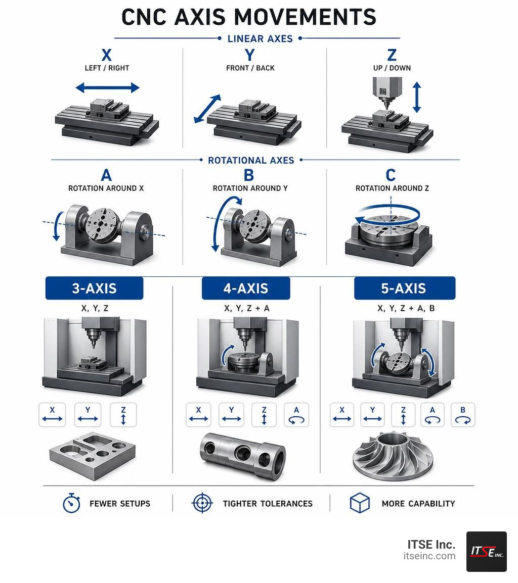
A CNC machine axis is a direction of controlled movement. Each axis adds one degree of freedom to how the cutting tool or workpiece can be positioned. Here’s how the axes break down:
| Axis | Type | Movement |
|---|---|---|
| X | Linear | Left / Right |
| Y | Linear | Front / Back |
| Z | Linear | Up / Down |
| A | Rotational | Rotation around X |
| B | Rotational | Rotation around Y |
| C | Rotational | Rotation around Z |
- 3-axis machines move in X, Y, and Z only — good for simple parts
- 4-axis machines add A-axis rotation — useful for cylindrical or multi-side parts
- 5-axis machines add two rotational axes — ideal for complex, multi-face geometry in a single setup
More axes = fewer setups, tighter tolerances, and parts that were previously impossible to machine in one go.
If you run a tube or pipe operation, this matters directly. The difference between a 3-axis and a 5-axis machine can mean the difference between four separate setups and one — and that gap shows up in your cycle times, scrap rates, and labor costs.
I’m Jarek Szpakowski, and at ITSE Inc. in Lake Zurich, IL, I’ve spent years applying CNC machine axis configurations to precision tube mill equipment, ID/OD scarfing systems, and custom components for industrial manufacturers. That hands-on experience is the foundation of everything covered in this guide.
Understanding the Fundamentals of a CNC Machine Axis
At its core, a cnc machine axis is about controlled, repeatable movement. To understand how these movements coordinate to shape solid metal, we have to look under the hood at the geometry and the mechanical components that make it happen.
The Cartesian Coordinate System and Machine Geometry
Every standard CNC machine relies on the Cartesian coordinate system to locate points in three-dimensional space. This system uses three perpendicular (orthogonal) lines—the X, Y, and Z axes—to establish a coordinate grid.
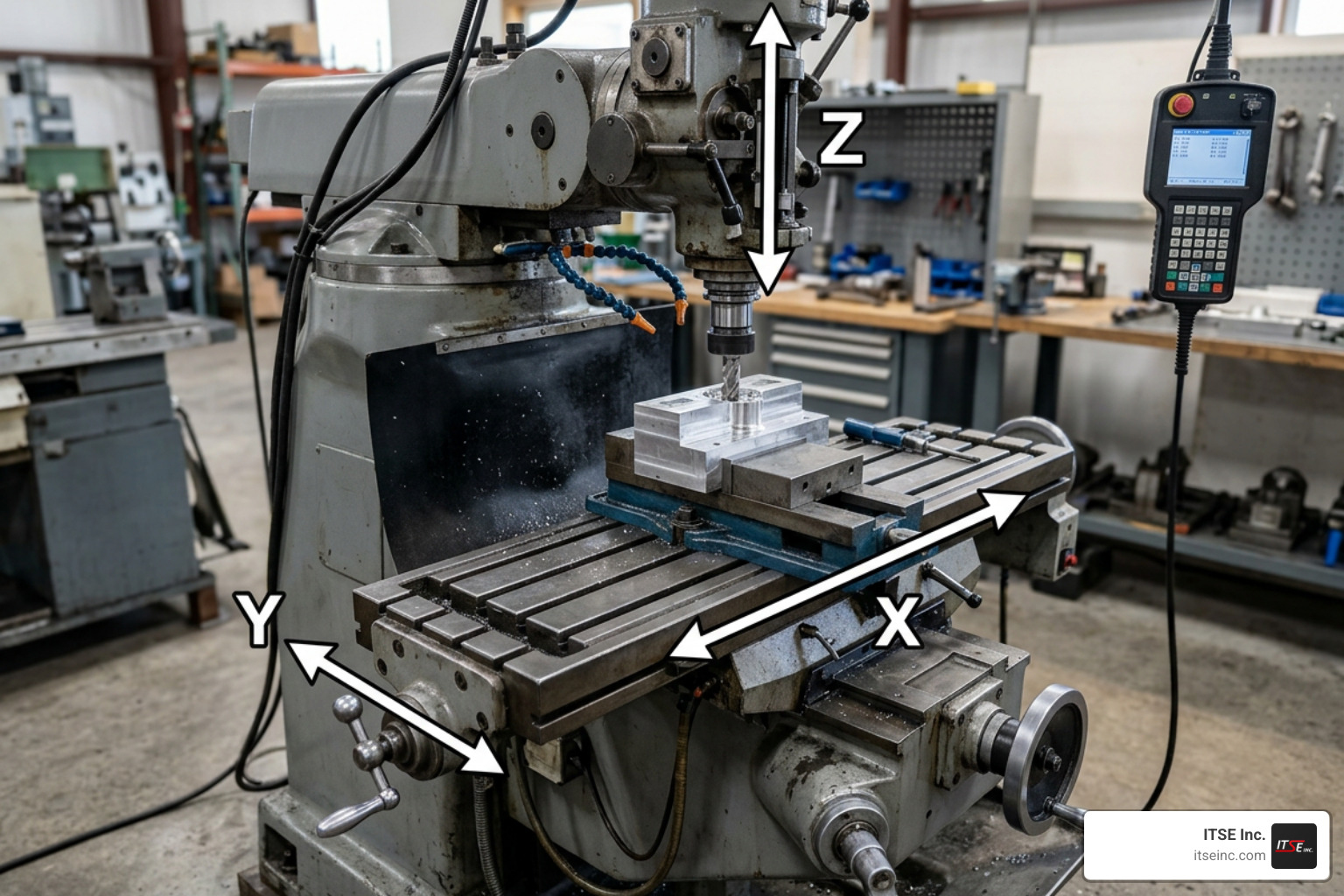
- Linear Axes (X, Y, Z): These axes move in straight lines. The Z-axis is traditionally aligned with the machine’s spindle (the rotating component holding the tool). The X-axis typically moves left to right, and the Y-axis moves front to back.
- Rotational Axes (A, B, C): When a machine needs to tilt or rotate the part or the tool, it uses rotational axes. These are defined by how they rotate around the linear axes: the A-axis rotates around X, the B-axis rotates around Y, and the C-axis rotates around Z.
Kinematics: Joints vs. Axes
To make these movements precise, the machine’s controller relies on kinematics. In CNC control, there is an important distinction between physical joints and Cartesian axes:
- Joints are the physical, mechanical degrees of freedom driven by individual motors. This could be a linear guide rail driven by a high-precision ballscrew, like the PRO Ballscrew Z Axis | Avid CNC, or a rotary table driven by a direct-drive motor.
- Axes are the coordinate letters (X, Y, Z, A, B, C) written into the G-code program.
In simple machines, there is a 1:1 relationship between joints and axes (known as trivial kinematics). For example, joint 0 moves the physical X-axis, joint 1 moves Y, and joint 2 moves Z. However, in more advanced setups—such as parallel kinematics, gantry systems with dual motors on a single axis, or complex multi-axis configurations—the machine controller must use non-trivial kinematics to mathematically translate Cartesian coordinates into physical joint movements. You can explore a deep dive into these mathematical transformations in this Technical guide on CNC machine kinematics.
The Role of the G-Code Interpreter
The brain of any CNC system is its controller, which runs an interpreter to read G-code. This software translates programmed coordinates into electrical signals that drive the motors. According to the Overview of CNC machining center components, the interpreter doesn’t just manage the axes; it coordinates them with other critical machine components, including:
- The Spindle: Controlling speed (RPM) and direction.
- Coolant Systems: Activating flood, mist, or through-spindle coolant.
- Tool Changers: Managing tool carousels and automatic tool changes (ATC).
- Feed Overrides: Allowing operators to adjust speed and feed rates on the fly.
For those interested in building or customizing their own motion systems, open-source projects like the Universal CNC Axis – Open Source Ecology demonstrate how modular, scalable linear axes can be designed using standard bearings and belt or screw drives to achieve precise positioning.
How a CNC Machine Axis Dictates Part Complexity
The number of axes on a machine directly limits the geometry of the parts you can make. In subtractive manufacturing, the cutting tool must physically access the material to remove it.
With a standard 3-axis setup, the tool approaches the workpiece from a single, fixed direction (usually straight down along the Z-axis). If you need to cut a pocket on the side of the part, or drill an angled hole, you have to stop the machine, manually unclamp the part, rotate it, re-clamp it, and re-zero the machine.
Every time you manually reposition a part, you introduce the risk of human error. If the part is misaligned by even a fraction of a millimeter in the second setup, the features on the top won’t align perfectly with the features on the side.
By adding rotational axes, you increase the machine’s “degrees of freedom.” This allows the cutting tool to maintain an optimal angle relative to the workpiece surface, eliminating manual setups and allowing for the creation of organic, free-form shapes, undercuts, and complex compound angles. For manufacturers in Lake Zurich looking to optimize their production, understanding this relationship is key to choosing the right partner. You can find More info about Lake Zurich CNC machining to see how local shops leverage these capabilities.
Comparing 3-Axis, 4-Axis, and 5-Axis CNC Configurations
Choosing the right machine configuration requires balancing part geometry, setup times, and overall cost. Below is a practical comparison of the three most common CNC setups:
| Capability / Feature | 3-Axis CNC | 4-Axis CNC | 5-Axis CNC |
|---|---|---|---|
| Axes of Motion | X, Y, Z (Linear) | X, Y, Z + A or B (Rotational) | X, Y, Z + two of A, B, C |
| Setup Requirements | High (Multiple manual setups for multi-sided parts) | Medium (Fewer setups; parts rotated on an indexer) | Low (Typically 1 to 2 setups total) |
| Surface Finish | Standard (Limited by fixed-angle stepovers) | Improved (Better tool positioning on curved surfaces) | Superior (Tool can maintain constant contact angle) |
| Cycle Times | Longer for complex parts due to manual handling | Shorter for cylindrical or indexed parts | Shortest for highly complex, multi-sided components |
| Programming Complexity | Low (Simple 2.5D and 3D tool paths) | Moderate (Requires rotary axis wrapping or indexing) | High (Requires advanced CAM software and post-processors) |
3-Axis Machining: The Industry Workhorse
A 3-axis machine operates on the X, Y, and Z plane. The workpiece remains stationary on the machine table while the cutting tool moves along these three linear paths.
- Best For: Flat plates, brackets, simple enclosures, and basic molds.
- Limitations: Cannot machine undercuts or features on multiple sides without manual repositioning. Deep pockets often require long, slender tools that are prone to deflection and vibration, leading to a poorer surface finish.
4-Axis Machining: Adding Rotation
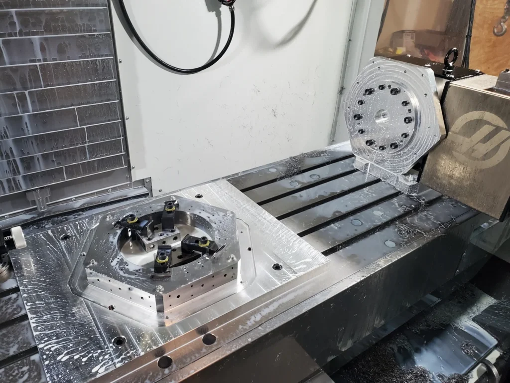
A 4-axis machine adds a rotary axis (usually the A-axis, rotating around the X-axis) to the standard linear movements. This is typically achieved by mounting a rotary table or indexer onto the 3-axis machine bed.
- Best For: Camshafts, gears, continuous engraving on cylindrical surfaces, and parts that require machining on four sides.
- How it Works: The machine can operate in two modes: indexed (where the 4th axis rotates the part to a specific angle and locks it in place before cutting) or continuous (where the rotary axis moves simultaneously with the linear axes to cut complex spirals or profiles).
5-Axis Machining: The Pinnacle of Flexibility
A 5-axis machine utilizes three linear axes and two rotational axes (such as A and C, or B and C). This allows the tool to approach the workpiece from virtually any direction.
The productivity advantages here are massive. For example, standard multi-axis setups allow shops to complete complex jobs in just 1 to 2 setups, compared to the 4 to 10 setups that would be required on a traditional 3-axis machine. By completing five of the six sides of a part in the very first operation, you drastically reduce cycle times, eliminate human error during manual repositioning, and maintain incredibly tight geometric tolerances between features on different faces.
Choosing the Right CNC Machine Axis Configuration for Your Shop
How do you decide which configuration is right for your specific project? It comes down to four primary factors:
- Part Geometry: If your parts are flat, boxy, or only require machining on one side, a 3-axis machine is the most cost-effective choice. If your parts have complex curves, deep angled cavities, or features on multiple faces, 5-axis machining is highly recommended.
- Production Volume: For high-volume production of multi-sided parts, the setup reduction offered by a 5-axis machine easily offsets the higher initial machine and programming costs. For short runs of simple parts, the quick setup of a 3-axis machine is hard to beat.
- Tolerance Requirements: When features on different sides of a part must align within extremely tight tolerances, machining them in a single setup on a 5-axis machine is the best way to guarantee accuracy.
- Programming and Operator Skill: 5-axis machines require specialized CAM software, advanced post-processors, and highly skilled operators. If your shop lacks this infrastructure, a 3-axis or 4-axis setup may be more practical.
If you are looking for More info about precision 5-axis CNC machining, we can help you evaluate your designs to determine the most efficient manufacturing path.
Matching your part’s geometric needs to the machine’s axis capabilities prevents you from overpaying for unnecessary complexity. This holds true whether you are looking to optimize your internal production or partnering with a specialized precision machine shop to handle your most demanding manufacturing requirements.
Advanced Multi-Axis Machining: 5-Axis Types and Kinematics
Not all 5-axis machines are built the same way. The physical arrangement of the rotational axes—known as the machine’s kinematics—affects its weight capacity, part size limitations, and rigidity.
The Three Main 5-Axis Configurations
- Trunnion Table (Table-Table):
In this configuration, both rotational axes are located in the machine table. The spindle moves only linearly (X, Y, Z), while the table tilts and rotates the workpiece.
- Pros: Excellent torque and rigidity; ideal for heavy material removal on smaller, compact parts.
- Cons: Because the table must tilt and spin, the maximum weight and size of the workpiece are limited.
- Swivel Head (Head-Table):
This hybrid setup puts one rotational axis in the spindle head (which tilts) and one in the table (which rotates).
- Pros: Offers a larger work envelope than a trunnion machine; can handle heavier workpieces because the table only rotates and does not tilt.
- Cons: The tilting spindle head can be limited in its angular reach compared to a full trunnion table.
- Gantry / Head-Head:
In a head-head configuration, both rotational axes are located in the spindle head. The workpiece remains completely stationary on a large fixed bed.
- Pros: Best for massive, heavy components (such as aerospace wing spars or large automotive molds) where moving the workpiece is physically impractical.
- Cons: These machines are typically very large, expensive, and require careful calibration to maintain accuracy across long travels.
Understanding RTCP Mode and Gimbal Lock
To make 5-axis machining precise, advanced CNC controllers use RTCP (Rotational Tool Center Point) mode.
In standard programming, if you tilt a rotary axis, the tip of the cutting tool moves away from its target coordinate because of the physical swing radius. Without RTCP, the programmer would have to calculate this offset manually in the CAM software for every single movement. With RTCP enabled, the machine controller automatically calculates this geometric shift in real time. It makes instantaneous, microscopic adjustments to the X, Y, and Z axes so that the physical tool tip stays locked exactly where it needs to be, regardless of how the table tilts or the head swivels. You can read more about how RTCP and tool vectors are configured at the firmware level in the Robot CNC 5 axis | Duet3D Documentation.
Another kinematic challenge in multi-axis machining is Gimbal Lock (or singularity). This occurs when two rotational axes align parallel to one another, effectively losing one degree of freedom. When a machine approaches a singularity, the controller may attempt to spin a rotary axis at an infinite speed to maintain the tool path, causing the machine to stall or fault. Advanced CAM software and modern controllers are designed to detect and program around these singularity zones to keep cutting smooth and continuous.
Implementation: Tooling, Workholding, and CAM Programming
Investing in a multi-axis CNC machine is only half the battle; you also need the right tooling, workholding, and software to unlock its full potential.
CAM Software and Collision Avoidance
Programming a 5-axis machine is significantly more complex than programming a 3-axis mill. It requires advanced Computer-Aided Manufacturing (CAM) software to generate the tool paths and calculate the continuous movements of all five axes.
The biggest risk in 5-axis machining is a collision. Because the spindle head and the workholding table are moving dynamically in close proximity, a programming error can result in a catastrophic crash. Modern CAM software includes robust simulation and collision avoidance features. Before a program ever reaches the machine shop floor, the software runs a virtual simulation of the entire cut, checking for clearance issues between the tool holder, the spindle head, the workpiece, and the fixtures.
Tooling Best Practices
To get the most out of multi-axis machining, standard tooling practices must be upgraded:
- Use Shorter Tools: Because a 5-axis machine can tilt the part to avoid obstructions, you no longer need long, thin tools to reach deep pockets. Shorter tools are stiffer, reduce vibration, and allow for much faster feed rates and better surface finishes.
- Shrink Fit Holders: For high-speed machining (spindle speeds above 10,000 RPM), shrink fit tool holders are highly recommended. They provide exceptional concentricity (minimal runout) and clamping force, which is critical when performing continuous multi-axis profiling.
Workholding for 5-Axis Machining
Traditional vises block access to the sides of a part, defeating the purpose of having five axes of movement. 5-axis workholding requires fixtures that elevate the part off the table to maximize tool clearance.
- Dovetail Fixtures: These fixtures grip a small, sacrificial dovetail machined into the bottom of the raw stock. This provides rock-solid clamping force while leaving five full sides of the part completely exposed for machining.
- Self-Centering Vises: These compact vises clamp the bottom few millimeters of the workpiece, maximizing access while keeping the part centered over the rotary axis.
Frequently Asked Questions About CNC Axes
What is the difference between simultaneous 5-axis and 3+2 machining?
The difference lies in whether the rotational axes move during the cutting process:
- Simultaneous 5-axis machining moves all five axes (three linear and two rotational) at the same time during the cut. This is required for complex, organic shapes like turbine blades, impellers, and advanced aerospace components.
- 3+2 machining (or indexed 5-axis) uses the two rotational axes to tilt and rotate the workpiece to a specific angle. Once in position, the rotary axes lock in place, and the machine cuts the feature using standard, highly rigid 3-axis (X, Y, Z) movements. This is highly efficient for multi-sided parts that do not have organic, curved geometries.
How does increasing the number of axes affect programming and setup times?
Increasing the number of axes represents a trade-off between office prep time and shop-floor execution time:
- Setup Times: 5-axis machining drastically reduces setup times on the shop floor. A part that used to require four different fixtures and manual alignments on a 3-axis mill can now be completed in a single setup.
- Programming Times: Because of the complex kinematics, tool paths, and collision risks, programming a 5-axis job in CAM software takes longer and requires a more experienced programmer than a standard 3-axis job.
What industries benefit most from multi-axis CNC technology?
Any industry that requires high precision, complex geometries, or rapid production of multi-sided parts benefits from multi-axis technology:
- Aerospace: Engine components, turbine blades, and structural brackets.
- Medical: Complex orthopedic implants, bone screws, and surgical instruments.
- Automotive: High-performance engine blocks, intake manifolds, and prototyping.
- Tube and Pipe Manufacturing: Complex roll tooling, custom dies, and heavy-duty tube mill components that require perfect geometric alignment across multiple faces.
Conclusion
Understanding the capabilities of the cnc machine axis is essential for modern manufacturing. While 3-axis machines remain the cost-effective workhorses for simpler, flat components, upgrading to 4-axis or 5-axis configurations unlocks a level of geometric freedom, precision, and efficiency that traditional setups simply cannot match. By reducing setups, cutting cycle times, and eliminating human positioning errors, multi-axis machining is the key to smarter, faster production.
At ITSE Inc. in Lake Zurich, IL, we apply these advanced manufacturing principles to build high-performance, US-made equipment for the tube and pipe industry. Whether you need precision OD bead choppers, ID scarfing systems, or custom-tailored tube mill equipment, our commitment to quality and engineering excellence ensures your operation runs at peak efficiency.
Ready to optimize your production with precision-engineered solutions? Explore our professional CNC machining services or contact us today to discuss your next project.