
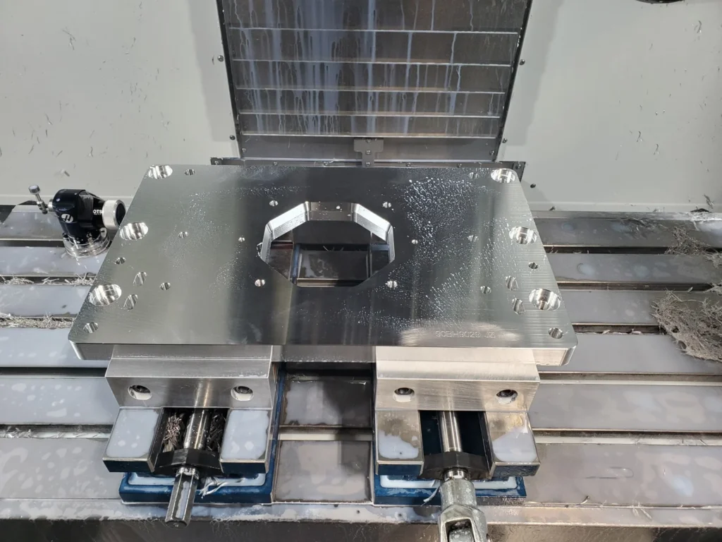
What CNC Machining Is — and Why It Matters for Precision Manufacturing
CNC machining is a subtractive manufacturing process where computer-controlled cutting tools remove material from a solid block to create precision parts. Here’s a quick overview:
| What | Details |
|---|---|
| What it stands for | Computer Numerical Control |
| How it works | Pre-programmed code (G-code/M-code) guides cutting tools automatically |
| Common processes | Milling, turning, drilling, grinding |
| Materials | Metals (aluminum, steel, titanium) and plastics (PEEK, Nylon, Delrin) |
| Typical tolerances | ±0.005″ standard; as tight as ±0.0001″ for precision work |
| Key industries | Aerospace, automotive, medical, tube and pipe manufacturing |
Whether you need a one-off prototype or a high-volume production run, CNC machining delivers consistent, repeatable accuracy that manual methods simply can’t match. It’s one of the most widely used manufacturing processes in the world — and for good reason.
For tube and pipe manufacturers specifically, precision-machined components are critical. Weld bead removal systems, scarfing tools, and bead choppers all depend on tight-tolerance machined parts to perform reliably under continuous production loads. When those parts are inconsistent, your whole line pays the price.
I’m Jarek Szpakowski, and through ITSE Inc. — our precision CNC machining shop in Lake Zurich, IL — I’ve spent years engineering custom tube mill equipment, ID/OD scarfing systems, and bead chopper solutions for manufacturers across the U.S. In this guide, I’ll walk you through everything you need to know to make smarter decisions about CNC machined parts and equipment.
What is CNC Machining and How Does It Work?
At its core, cnc machining is like a high-tech sculptor. Instead of a hammer and chisel, it uses high-speed rotating cutting tools to carve a finished part out of a raw block of material (known as the workpiece or billet). Because it removes material to reveal the final shape, it is classified as a subtractive manufacturing process.
But how do these machines know exactly where to cut? The magic lies in the software and the code.
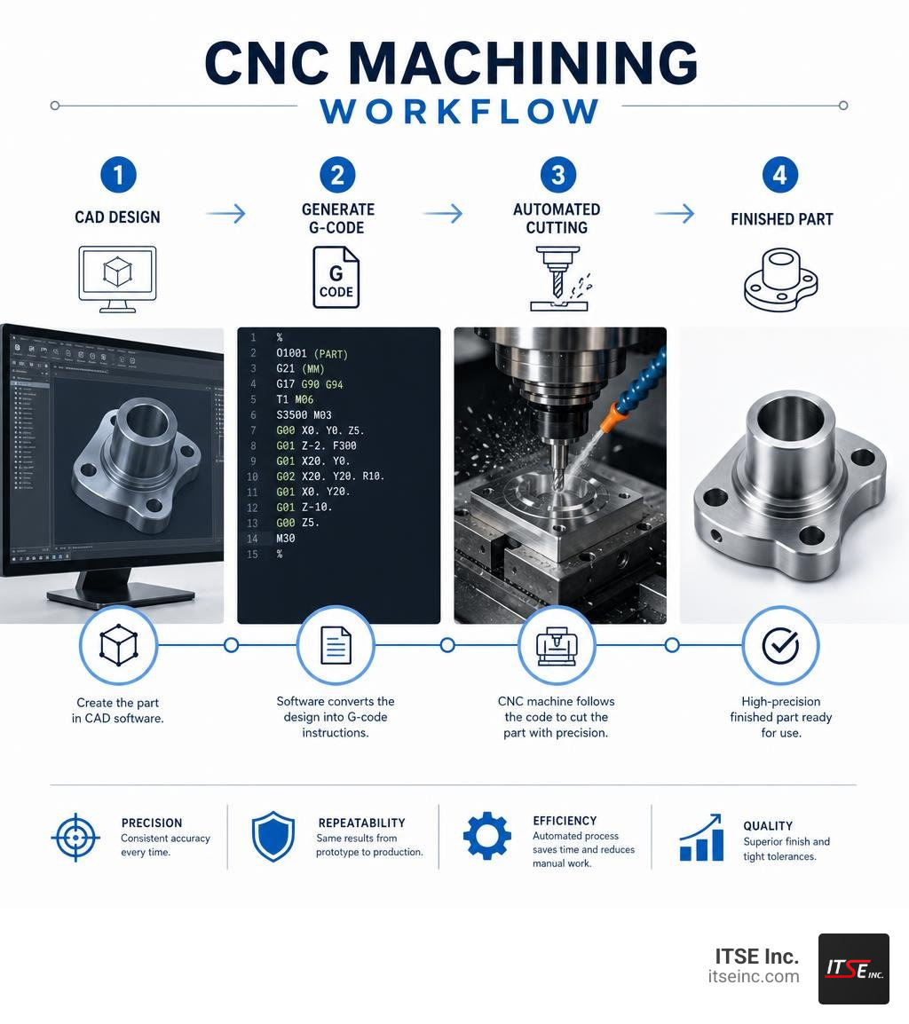
The journey of a machined part begins with Computer-Aided Design (CAD). Engineers design a 3D model of the part using CAD software. Once the design is finalized, it is imported into Computer-Aided Manufacturing (CAM) software. The CAM software analyzes the geometry and translates it into a language the CNC machine can understand. This language consists of two primary types of instructions:
- G-code (Geometric Code): This controls the movement of the machine. It tells the cutting tool where to go, how fast to move (feed rate), how deep to cut, and what path to follow along the X, Y, and Z axes.
- M-code (Miscellaneous Code): This manages the auxiliary functions of the machine. It tells the system when to turn the spindle on or off, when to activate the liquid coolant (essential for keeping tools from melting), and when to perform automatic tool changes.
Once the program is loaded, the machine executes the instructions with incredible speed and repeatability. Modern industrial CNC setups rely on closed-loop systems. Unlike basic open-loop systems that simply send movement signals and “hope for the best,” closed-loop systems feature continuous feedback sensors. These sensors constantly monitor the tool’s actual position and velocity, sending real-time data back to the computer controller. If the tool deflects even a fraction of a millimeter due to material resistance, the controller instantly corrects the path.
This high level of automation and real-time adjustment is why we rely on our in-house CNC Machining capabilities to manufacture robust tube mill equipment that stands up to the harshest factory floor environments in the Chicago area.
Types of CNC Machines and Their Applications
Not all CNC machines are built the same. Depending on the geometry of the part, the material being cut, and the required volume, different machine configurations are utilized to optimize production.
CNC Milling and Turning Centers for CNC Machining
The two workhorses of the machining world are milling machines and turning centers (lathes).
- CNC Milling: In a milling machine, the raw material remains stationary (clamped securely in a vise or fixture) while a cutting tool rotates at high speeds and moves along multiple axes to shave away material.
- 3-Axis Mills: The tool moves along the traditional Cartesian coordinate system (X, Y, and Z axes). This is the most common and cost-effective milling method, perfect for simpler geometries.
- 4-Axis Mills: These add a rotational axis (typically the A-axis, rotating around the X-axis), allowing the workpiece to spin. This is incredibly useful for cutting features on curved surfaces or around cylinders.
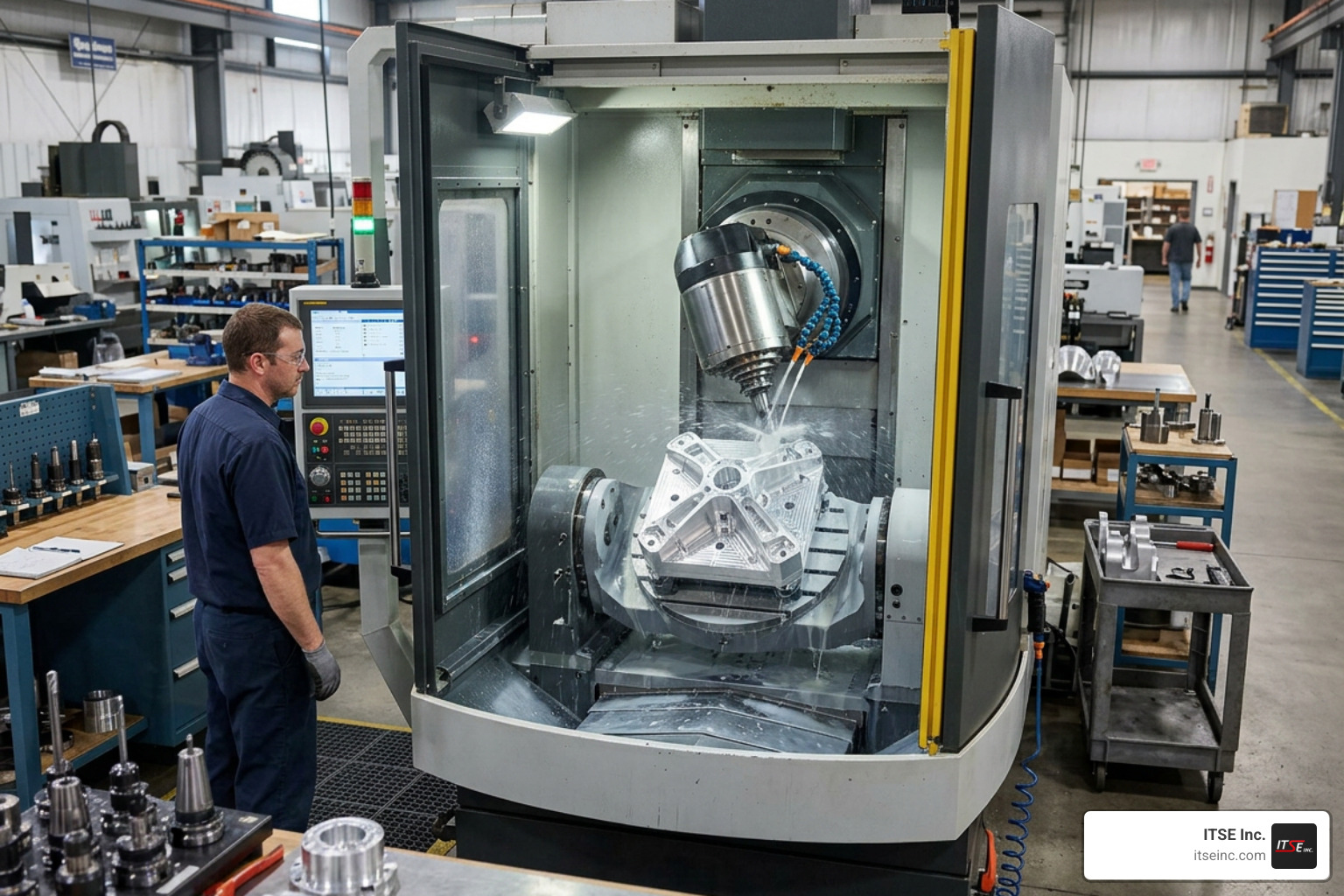
- 5-Axis Mills: These represent the pinnacle of milling technology. The tool or the workpiece can rotate along two additional axes (A, B, or C) while simultaneously moving along X, Y, and Z. This allows the cutting tool to approach the part from virtually any angle, enabling highly complex geometries like turbine impellers or medical implants in a single setup.
- CNC Turning (Lathes): In turning, the process is reversed. The raw material is chucked into a spindle and rotated at high speeds while a stationary cutting tool is pressed against it to carve away material. This is the ideal method for creating cylindrical or symmetrical parts like shafts, flanges, and custom pins.
To bridge the gap between these two processes, advanced shops utilize mill-turning centers. These hybrid machines combine a rotating lathe spindle with live milling tooling, allowing a part to be turned and milled on the same machine without moving it to a different station. For complex projects, choosing the right approach is key to maximizing efficiency and maintaining tight tolerances.
Other Specialized CNC Equipment
Beyond standard mills and lathes, the modern manufacturing floor utilizes a variety of specialized computer-controlled equipment:
- Live Tooling & Automatic Tool Changers (ATCs): Modern milling and turning centers feature ATCs that can hold dozens of different tools (drills, end mills, taps, reamers) and swap them out in seconds without operator intervention.
- High-Speed Spindles: Essential for machining soft metals like aluminum or micro-features in plastics, high-speed spindles can rotate at upwards of 20,000 to 40,000 RPM to achieve pristine surface finishes.
- Custom Workholding: High-precision parts require specialized workholding solutions like custom soft jaws, vacuum tables, or magnetic chucks to hold irregular geometries securely without deforming the material.
- Electrical Discharge Machining (EDM): Using electrical sparks to erode material rather than physical cutting force, wire and sinker EDMs are used to cut ultra-hard metals or create extremely sharp internal corners that physical end mills cannot reach.
At ITSE Inc., we integrate these specialized machining capabilities to produce our high-performance Products, ensuring that every component of our tube mill machinery is perfectly aligned and built to last.
Comparing Subtractive Manufacturing to Other Methods
When designing a part, engineers must choose between subtractive manufacturing (CNC), additive manufacturing (3D printing), and traditional manual machining. Each has its place, but understanding the trade-offs in production volume, dimensional accuracy, and lead times is critical to keeping projects on budget.
CNC Machining vs. 3D Printing and Traditional Machining
- 3D Printing (Additive): 3D printing builds parts layer-by-layer from plastic filaments, resins, or metal powders. It is fantastic for rapid prototyping of highly complex, organic shapes that are physically impossible to machine. However, 3D-printed parts generally lack the structural strength, isotropic material properties, and tight dimensional tolerances of CNC-machined parts.
- Traditional (Manual) Machining: Manual milling and turning rely entirely on a human operator turning handwheels to guide the machine. While great for quick, simple modifications or repair work on a single part, manual machining cannot match the speed, complexity, or repeatability of CNC systems for production runs.
Here is a quick comparison table to highlight the differences:
| Manufacturing Method | Dimensional Accuracy | Material Strength | Best Production Volume | Setup Time & Cost |
|---|---|---|---|---|
| CNC Machining | Extremely High (down to ±0.0001″) | Excellent (uses solid, wrought raw material) | Low to Medium (1 to 10,000+ parts) | Moderate Setup / Low Unit Cost |
| 3D Printing | Moderate (typically ±0.005″ to ±0.010″) | Moderate (anisotropic, layer-line weaknesses) | Very Low (1 to 10 prototypes) | Very Low Setup / High Unit Cost |
| Manual Machining | High (dependent on operator skill) | Excellent (uses solid raw material) | Very Low (1-5 simple parts) | Low Setup / High Labor Cost |
Key Advantages and Constraints
Like any manufacturing process, CNC has its strengths and limitations.
The Advantages:
- Exceptional Repeatability: Once a program is written and proven, the machine can produce the exact same part thousands of times with virtually zero deviation.
- Superior Material Properties: Because parts are carved from solid, fully-dense blocks of extruded or cast metal/plastic, they possess excellent mechanical strength and thermal conductivity.
- High Precision: CNC systems easily hold tolerances that are a fraction of the width of a human hair.
The Constraints:
- Material Waste: Because it is subtractive, a significant portion of the starting block is turned into chips. For expensive materials like titanium, this waste can drive up costs.
- Tool Access Restrictions: Cutting tools are round and must physically reach the area being cut. This means 90-degree square internal corners are impossible to machine directly (they will always have a radius left by the tool), and deep, narrow cavities are highly difficult to reach without specialized tooling.
- Higher Initial Setup Costs: Writing the G-code program, setting up the workholding, and calibrating the machine takes time. This makes a single CNC-machined prototype relatively expensive compared to a 3D print, though the unit cost drops dramatically as production volume increases.
Materials, Design Guidelines, and Industry Applications
Selecting the right material and optimizing your part design are the two most effective ways to lower your manufacturing costs and ensure your parts perform flawlessly in the field.

Material Selection for Metals and Plastics
CNC machines can process a vast array of materials, from soft plastics to hardened superalloys. Here are some of the most common materials used in industrial manufacturing:
- Aluminum 6061-T6: The absolute gold standard of CNC machining. It is highly machinable, offers an excellent strength-to-weight ratio, resists corrosion, and anodizes beautifully. It is our go-to choice for custom brackets, structural components, and non-wear parts.
- Stainless Steel (304 & 316): Highly valued for its corrosion resistance and strength. It is tougher to machine than aluminum and requires slower cutting speeds, making it more expensive, but it is essential for food processing, marine, and medical applications.
- Titanium: Extremely strong, lightweight, and biocompatible, but notoriously difficult to machine due to its high strength and low thermal conductivity (which traps heat at the cutting edge of the tool).
- Delrin (Acetal): An engineering plastic known for its high stiffness, low friction, and exceptional dimensional stability. It machines beautifully and is often used for gears, bushings, and wear pads.
- PEEK: An advanced thermoplastic that can withstand extreme temperatures and chemical exposure. It is commonly used in aerospace and medical device applications where metal cannot be used.
The versatility of aluminum makes it a cornerstone of modern product design, especially when high strength-to-weight ratios and corrosion resistance are required.
Design for Manufacturability (DFM) and Tolerances
To get the most out of cnc machining, you should design your parts with the manufacturing process in mind.
Following a few simple DFM rules can prevent machining errors and save you thousands of dollars:
- Avoid Sharp Internal Corners: Because milling cutters are round, they cannot machine a sharp internal 90-degree vertical corner. Always design internal corners with a radius. Ideally, make the corner radius slightly larger than the radius of the cutting tool (e.g., if using a 1/4″ end mill, design a 0.135″ radius rather than exactly 0.125″ to reduce tool wear and chatter).
- Limit Cavity Depth: Deep cavities require long cutting tools, which are prone to deflection, vibration, and breakage. As a rule of thumb, keep the depth of a cavity to no more than 4 times its width.
- Maintain Minimum Wall Thickness: Thin walls can vibrate during machining, leading to poor surface finishes or warped parts. Keep metal walls at least 0.8 mm (0.031″) thick and plastic walls at least 1.5 mm (0.059″) thick.
- Use Standard Tolerances: Unless a tight fit is absolutely critical (such as a bearing press-fit), specify standard tolerances like ±0.005″ (±0.125 mm). Demanding tighter tolerances requires specialized inspection, slower machining speeds, and more frequent tool changes, which rapidly inflates costs.
Key Industries and Cost Factors
CNC machining is the backbone of several major industries:
- Aerospace: Requires lightweight, high-strength parts (like titanium brackets and turbine blades) machined to ultra-tight tolerances with extensive quality documentation.
- Medical Devices: Surgical instruments, orthotic implants, and diagnostic equipment depend on the sterile, precise nature of CNC-machined PEEK, titanium, and stainless steel.
- Automotive: From engine blocks and transmission shafts to lightweight suspension brackets, CNC machining supports both rapid prototyping and high-volume automotive production.
- Tube and Pipe Mills: Heavy industrial equipment relies on rugged, precision-ground tool steels and wear-resistant components to keep high-speed tube mills running without interruption.
When it comes to cost, the primary drivers are setup time, machining time, and material cost. Because setting up a CNC machine can take several hours, producing a single part is highly inefficient. However, because the machine runs automatically once set up, ordering in larger batches allows you to spread that setup cost across many parts, dramatically reducing the cost per unit.
If you are looking for highly localized precision services in the Chicago area, we invite you to explore Top Precision CNC Machining Services in Lake Zurich for Your Manufacturing Needs. Local manufacturers in suburbs like Addison, Schaumburg, and Elk Grove Village have a wealth of regional expertise at their disposal. This deep manufacturing heritage in Illinois is something we are proud to be a part of here at ITSE Inc.
Frequently Asked Questions
What skills are required to operate these machines?
Operating modern CNC machinery is a blend of computer science, engineering, and hands-on craftsmanship. A skilled CNC machinist must be able to read complex engineering blueprints, understand geometric dimensioning and tolerancing (GD&T), set up workholding fixtures, and program or edit G-code. Many machinists start their careers through dedicated vocational programs, such as Goodwin University’s accelerated manufacturing programs, where students can earn a career-ready certificate in as little as 6 months. Obtaining industry-standard credentials, like a National Institute for Metalworking Skills (NIMS) certification, is highly valued on the shop floor.
How do I get started with custom manufacturing services?
Getting custom parts manufactured is easier than ever. The typical process follows these steps:
- Prepare Your CAD Model: Export your 3D design into a standard format, with STEP (.stp) being the most widely accepted industry standard.
- Create a Technical Drawing: For parts with threads, critical tolerances, or specific surface finishes, provide a 2D PDF drawing alongside your 3D model.
- Submit for DFM & Quote: Upload your files to a manufacturer. A team of engineers will perform a Design for Manufacturability (DFM) review to ensure your part can be made efficiently and provide a detailed quote.
What is the difference between 3-axis and 5-axis machining?
In 3-axis machining, the cutting tool moves along the X, Y, and Z axes while the workpiece remains fixed. If you need to machine features on multiple sides of a part, the operator must manually stop the machine, rotate the part, re-clamp it, and recalibrate the tool coordinate system.
In contrast, 5-axis machining allows the cutting tool to move along five different axes simultaneously. By rotating the part or the spindle head, the machine can access five sides of a part in a single setup. This dramatically reduces setup time, eliminates human alignment errors, and allows for the creation of highly complex, curved geometries. For local businesses seeking these advanced capabilities, we offer specialized Precision 5 Axis CNC Machining Services in Lake Zurich.
Conclusion
At ITSE Inc., we believe that precision isn’t just a specification on a drawing — it’s the foundation of operational reliability. Whether we are designing custom tube mill equipment, manufacturing high-performance OD bead choppers, or engineering Advanced Tube Mill Scarfing systems, we apply our deep expertise in high-tolerance machining to deliver U.S.-made quality that keeps your production lines running smoothly.
If you are looking for a trusted partner to bring your complex designs to life, optimize your manufacturing processes, or supply rugged, custom-engineered tooling, we are here to help. Reach out to our engineering team today to explore our full range of CNC Machining Services and let’s build something exceptional together.